Truma Cleaning Mode Reset

By Tom McAllister
March 24, 2022

Please follow the instructions below to clear your Truma Hot Water Heater from Cleaning Mode.

Instructions

  • Power to the unit must be on from the main panel
  • The outside switch needs to be in the “ON” position
  • Turn rotary dial on inside switch to “ECO” or “Comfort” mode (these are the top 2 positions on the switch)
  • Open all the hot water faucets in the vehicle- let the water run until the yellow light stops flashing, this could take 15 minutes or so. (probably should be hooked to city water) (During this time you will hear the circulation pump turning off and on in approx. 30 second intervals this is normal. The burner will not ignite)
  • Once the inside switch stops flashing turn off water
  • Turn rotary dial to the “off” position
  • Turn the rocker switch on the AquaGo to the “off” position wait 30 seconds
  • Turn rocker switch on the AquaGo back on
  • Turn the rotary dial to the “ECO” or “Comfort” mode
  • The unit should work normally at this time.

Waking up the dial:
After completing this process, if you notice the dial light is not turning on, please slowly rotate the dial clockwise then counter clockwise until the dial lights up.

Truma Error Code List

Pre-Purchase RV Inspection Checklist

Updated by Rick Werth February 2022

  • Make sure all Mercedes services are current
  • Confirm that all Recall items have been completed for all components
  • Confirm all manuals and original manufacturer tools are included

EXTERIOR

  • Roof Seals – Inspect the condition of the roof ladder (if applicable) for stability and safety. Climb on the roof and closely inspect seams, gaskets, and any other place where the roof material is cut or drilled. Check closely around air conditioner, vents, antenna, sewer vents, solar panels, end-caps and seams on the condition of the sealants. No bubbles, nails or protruding screws! Check for rust spots near cut-away roof joint.
  • Sidewalls & End Caps: Inspect the aging and general overall condition of the front and rear caps. Inspect for any damage, discoloration and delamination of the side walls and end cap components. Check condition of all sealants used on seams.
    Windows – Check closely around each window to make sure it has been properly sealed. A narrow gap between trim ring & frame is OK, but it should be nearly even all the way around. Look for any water penetration outside and inside.
  • Cab & Entry Doors – Check the gasket for proper adhesion and coverage. Check from inside that it is flush against the door jamb. Check keys, lock & unlock. Check that screen door opens smoothly alone, locks to main door easily and does not have gaps to let mosquitoes in. Look for any water penetration outside inside.
  • Basement Compartments – Open and close each door, checking for alignment and gasketing. Lock & unlock. All hinges should be tight and secure, latches should hold the door tightly closed and be easy to open. Look for any signs of moisture that might indicate water leakage. Check for corrosion or rust on exterior of compartments.
  • Utility Compartment – Where are the low point drains for the fresh water tank and water heater? Condition and operational?
  • Propane –  Visually inspect all hoses and pressure regulators for damage and age deterioration. Confirm that a leak test has been performed on tank, regulator and the complete system. Check the propane tank for excessive rust or corrosion, any damage.
  • House Batteries – Make sure the battery compartment is ventilated unless Lithium batteries are installed. Determine the age and condition of the batteries. Verify that battery cables are in good condition, and all connections are secure and free from corrosion.
  • Power & Electrical – Inspect the condition of the power cord and its connection ends. Remove the cover to the electrical box where the generator cable plugs in for correct wire nuts and lack of heat damage. Check for proper operation of Automatic Transfer Switch (ATS) if equipped. Remove cover panel of the 120-volt circuit breaker box to visually inspect the condition of the wiring, circuit breakers and grounding connections. Note any heat discoloration to the wiring and connections. Check condition of built in surge connector if equipped. Check to make sure that the chassis batteries are being charged when the chassis engine is on.
  • Paint & Siding – Sight down the sides for bumps, depressions or delamination. Check the paint finish. Check for surface smoothness (no indentations!), color variations in gel coat and paint and any place where paint coverage is marginal or paint bubbles.
  • Tires and Wheels – Inspect tires (incl. spare) and wheels for condition and any damage. Check tire pressure. Check the tire manufacturer date to determine age. Check tire valves. If equipped, check the Tire Pressure Management System (TPMS – Aftermarket)
  • Step – Inspect and test operation of automatic step.
  • Generator – Determine total operating hours. Check oil level. Determine last full service. Inspect hoses. Operate generator under a load to verify operation (air conditioner will create the correct amount of load), listening for any unusual sounds or vibration, letting the generator run 10 minutes. Test the voltage output and frequency (60 cycles). The electrical status panel should show the status of the generator and the presence of AC voltage.

SLIDE-OUT(s)

Exterior:

  • Check seals, retraction process and operation of slide-topper.
  • Operate slide(s) to confirm smooth operation.
  • Inspect slide roof and slide awning condition.
  • Check for proper routing of wires and cables under slide.

Interior:

  • Operate slide(s) to confirm smooth operation.
  • Check for any leaks water leak damage around slide
  • Check for light shining through or airflow with slide in or out.
  • Check Emergency Brake interlock.
  • Evaluate the attached wiring and utility harness that feed underneath the slideout room. Confirm that no screws or bolts are cutting into the flooring during operation.

AWNING

  • Operate for smooth operation.
  • Inspect awning frames attachment points to wall and latching mechanisms.
  • Inspect the condition of fabric material of the awnings.

CHASSIS

  • Block tires. Crawl underneath to inspect for damage, excessive rust, brake lines, wiring, shock absorber attachments, and in general every place that a wire or pipe could rub against something that will cause a problem later.
  • Check for any fluid leakage.
  • Inspect exhaust pipe.
  • Inspect the frame, axles, springs, rims and other components for rust, oil stains and visible damage
  • Inspect the operating levels of all fluids: brake / hydraulic, transmission, fuel, oil, coolant.
  • Inspect engine drive belts.
  • Inspect steering for bent or damaged components or hydraulic leaks.
  • Test all lights and turn signals.

SOLAR COLLECTION SYSTEM

  • Inspect condition of all components of the system, including panels on the roof.
  • Inspect the solar power panel to determine status and condition of charging.
  • Determine type and age of solar batteries.

ENGINE

  • Verify oil level and condition on the dipstick
  • Note any engine issues or noises while running
  • Inspect for noticeable oil or exhaust leaks
  • Note the oil pressure reading on the dash gauges
  • Inspect radiator, coolant reservoir, and hoses
  • Check transmission fluid level. Look and smell fluid for any signs of overheating or contamination.

LEVELING SYSTEM

  • Verify the system operates properly by extending and retracting leveling system.
  • Note visual indications of hydraulic leaks or mechanic issues.

HITCH & SYSTEM

  • Inspect hitch for condition, welds, nuts/bolts are all secure.
  • Inspect and test 7-pin connector tow receptacle.

HOUSE SYSTEMS & INTERIOR

Test House Systems while plugged into shore power, on generator and on house batteries.

  • Power – Note the location of all AC and DC panels, fuses and breakers. Make sure the loads are labeled. Check all 110V outlets w/ tester for wiring, voltage and GFI. Check all 12V outlets for wiring.
  • Inverter – Make sure the inverter works and test outlets that are inverter powered.
  • Water Pump & City Water System – Water pump should pump for several seconds. Run water in the kitchen and bathroom sink and check that the pump will come back on. Listen to pump for any unusual noises. Turn off the pump, connect to city water supply.  Look for leaks at the inlet, under sinks and check the operation of all faucets / toilet and under RV.
  • Water Heater – Visually inspect burner assembly and gas exhaust system for blockages and insect infestation. Fill tank with water (if necessary) and verify operation on all heat sources – LP gas and 120-volt AC as equipped. Test water heater on propane first. A few seconds after you turn it on, you should hear the click of the igniter and the small pop when the burner lights. The red light should stay on until that process happens. Understand the operation of the bypass valve for winterizing. Determine if drain plug has been installed in water heater tank and working. If applicable, inspect bug cover screen (screen is highly recommended) on exterior of vent. Instant hot water systems operate differently, read the manual for operation testing.
  • Furnace – Turn the furnace on and set temp at least 10 degrees higher than ambient. In ~ 10 sec the furnace fan should come on. You should hear the click of the igniter and the sound of the burner. Hot air at about 110 degrees should be coming out of all vents. During testing check for smell of material getting too hot, or exhaust coming into the RV. Monitor for unusual noise or vibration of blower motor. Visually inspect air intake and exhaust assemblies for blockages and insect infestation. If applicable, inspect for bug cover screens on exterior of vents (screens highly recommended).
  • Refrigerator – Operate on all power sources – 120-volt AC, LP gas to ensure it is effectively cooling. Check condition of door frame, door gaskets, shelving, crisper drawers, door shelves and interior light. Ensure hot air is effectively vented.
  • TV, Entertainment, Antenna & Input Switching – Turn the TV(s) on. Review and understand the switching system that allows the selection of viewing channels on the TV. Test over-air channel reception for local stations. Rotate the antenna to maximize the quality of the picture. Understand the video selection switcher. Test radio, DVD, satellite, etc. systems as installed. Verify all remotes are present and operational.
  • Air Conditioner – Check air filters. Test system, after a couple of minutes, cool air, 20 degrees cooler than ambient, should be coming out of all registers. Listen for any unusual noises.
  • Microwave/Convection – Verify the rack and turn tables are installed and condition. Put a cup of cold water in the microwave and set the timer for 3 minutes. Make sure there are no unusual sounds coming from the system and water is hot.
  • Propane Stove – Turn on all burners to verify they work and there is also propane flow to operate the refrigerator and water heater. Operate and verify condition of the exhaust function and fan speeds. Inspect the filter and lighting.
  • Induction Stove – Using the appropriate cookware, check to see if the stove works.
  • Ceiling Mounted Fans & Ceiling Exhaust Vents – Inspect the condition of the blades and motor. Operate and verify condition of the blade direction and fan speeds.
  • Windows & Hatch – Open and close windows and hatch and operate the locks. Make sure emergency window operates smoothly. Ensure locks work effectively.
  • Floor Coverings – Inspect all corners and sides of carpet floor coverings to ensure that they are properly fastened.
  • Interior Conditions & Appearance – Inspect all ceilings, walls, interior doors and flooring for signs of water intrusion, surface damage and/or staining. Operate all windows and doors noting any deficiencies or missing components. Evaluate the window shades condition and functionality. Operate each blind and check for alignment. Look at valances and trim to be sure they are secured and matched. Check out the pull drapes.
  • Lighting – Operate all interior and exterior lighting, both on 12-volt and 120 volts.
  • Counter Tops – Inspect counter tops for alignment and fastening. Trim pieces should be tight. Inspect caulking quality everywhere. Check the installation of sinks and faucets.
  • Cabinets & Closet – Inspect and evaluate all cabinet doors, drawers and pull-out operation. Ensure secure locking. Inspect all areas of the kitchen, living room, bathroom, bedroom and storage area as for scratches, delamination or damage.
  • Furniture – Inspect the condition of the dinette table/booth, chairs, recliners and sofa (open & close). Note furniture fabric tears, delamination, discoloration and signs of excessive wear. Inspect mattresses for condition, damage or staining. Check for passenger seatbelt location and safety.
  • Shower – Inspect panels, curtains, etc. for effectiveness. Evaluate the seals around the frame work and doors for water leaks. Inspect for any stains or mold and mineral build up. Evaluate for any bad smells. Ensure shower head, hose, and controls work properly and are in good condition.
  • Toilet – Inspect that it is secured to the floor. Evaluate for any bad smells. Check the spray attachment for leaks. Inspect for any stains or mold or leaks. Evaluate the bowl seal that it holds water. Flush several times.

FRESH WATER SYSTEM

  • Verify the fresh water connections for the city water hookup are operational.
  • Test and verify proper filling of the fresh water tank.
  • Verify the onboard fresh water tank and pump system will operate and maintain pressure
  • Operationally test all fresh water fixtures inside and outside of the RV.
  • Inspect the water filtration system (if installed) for leaks and filter placement.
  • Determine the last time the system was sanitized.

WASTE WATER SYSTEMS (Gray and Black Water)

  • Operationally test and inspect both waste (gray and black) plumbing systems for leaks under the sinks, shower, around the toilet and discharge lines
  • Check the rubber connectors for the dump plumbing.
  • Identify the type drain valve controls
  • Verify the drain valves for both systems will maintain water in their tanks
  • Operate both drain valves and test for ease of operation
  • Verify the drain cap is in place and will hold waste water

LIFE SAFETY ITEMS

  • Test the Ground Fault Circuit Interrupter (GFCI) circuits receptacles they work.
  • Test all wall receptacles for correct polarity and ground fault.
  • Test the exterior skin for hot skin that would cause electrical shock.
  • Verify all safety emergency exit windows are operational.
  • Verify fire extinguisher is secure, up to date, in bracket and is fully charged.
  • Smoke/Fire Detector – Test and verify operation of units. Test backup battery condition.
  • Carbon Monoxide Detector – Test and verify operation of unit and note expiration date.
  • LP Gas Detector – Verify gas detection and audio alarm and note expiration date.
  • Verify the rubber grommet is properly sealed around LP gas line of water heater.

TEST DRIVE:

Perform the road test on a variety of road surface conditions, hills and at various speeds.

  • Do a walk around inspection of the RV to ensure all windows are closed, compartments are secured, awning is securely stowed, all running lights, headlamps are working. Check the interior to make sure all drawers are closed and latched, all compartments are secure and there are no loose objects laying in the coach. Secure all unsecured moveable objects. Make sure tables and counters are clear.
  • Operate the windshield washer and wiper, including delay.
  • Validate turn signals are functioning correctly.
  • Validate all exterior lights are functioning correctly.
  • Adjust the rear-view mirrors. Turn the ignition on, but don’t start the engine yet, so that you can see all the status and warning lights that might illuminate when you are driving.
  • Wait until `Wait to Start’ status light goes out. Engine should start easily within 2 seconds. Oil pressure should be present within 1 second (maximum 3 seconds) of starting. If no oil pressure, immediately shut engine down > we are done!
  • No warning lights should be illuminated on the dash at this time.
  • Turn on and adjust the rear-view camera monitor. Understand how to adjust it for day / night operation.
    Instrumentation should show normal reading throughout the test, be sure to check the gauges often.
  • Start with city-street driving, with little or no traffic. Perform several turns, watching the mirrors closely to get a feel for where the coach is relative to the road.
  • Once comfortable with low-speed maneuvering, head for the freeway. Leave yourself lots of room, because you don’t know how this coach accelerates! As you enter the on-ramp, floor the accelerator and you should get steady acceleration. Listen for any sounds that are not normal, like whines or grinds from under the coach, wind noise from the front door or slide out, flapping awnings, engine and transmission.
  • Bring the speed up to merge safely into traffic and go the speed limit. Observe gauges for normal range of operation. Observe the steering effort necessary to keep the coach going straight. If it takes too much steering then the wheel alignment is probably not correct.
  • Go at least two exits before turning off the freeway. Leave the rear-view monitor operating. Set and check Cruise Control
  • Brake Test: Do this test with space in front of the coach and on a flat surface. With the engine operating, apply the emergency brake, put gear selector in `Drive’ and apply a little pressure on the accelerator. The coach should not move. Release the emergency brake, drive forward at 10 mph and press the service brakes hard. It should come to a complete stop immediately, without screeching or pulling from one side to the other.
  • Turn on dash entertainment/GPS/Sirius XM etc. system and check all operations.
  • Turn on the dash A/C and let it run. After cooling is checked, turn dash heater on. Can do this on our test drive after the engine warms up.


Resetting Oil Service Indicator

Resetting Oil Service Indicator
2017 Mercedes Benz Sprinter

By Jeff Utschig
November 21, 2021

  1. Turn the key to the ON position
    • DO NOT start the vehicle
    • Wait for computer to setup
  2. On the circular interface – left side of steering wheel
    Press the LEFT MENU button to display MILEAGE (if not already displayed)
  3. Push the ▲ UP button to display the SERVICE-WRENCH ICON
  4. Hold down the 0 button – left of the tachometer – until you hear a beep
    • This could take ~ 15 – 30 seconds
  5. Then press RIGHT MENU button – on the same circular interface
    • Until the screen below is displayed

  6. Press the ▲ UP arrow until you see the SERVICE-WRENCH ICON again
  7. Briefly press and release the O button again
    • COMPLETE SERVICE will be the highlighted choice
    • Leave that as the choice
  8. Press the ▲ UP arrow until you see the display CONFIRM COMPLETE SERVICE & RESET 3S
  9. Press and HOLD the O button for ~ 3 seconds to reset
  10. It will then display SERVICE CONFIRMED
  11. Checking the service interval display (via the UP arrow)
    • Should display 20,000 miles

2008 to 2010 View Navion’s

December 19, 2021
By Bob Kelly

Introduction

The 2008- 2010 Winnebago View/Navions are built on the NCV3 Mercedes-Benz Chassis. Mercedes-Benz acquired the Chrysler Corporation in 1998 and later divested them in 2007. As a result, the Sprinter chassis was sold by the Dodge division of Chrysler. The chassis was manufactured in Europe as an incomplete chassis, and shipped to the United States, where Winnebago remanufactured it into a motor home.

The vehicle should be registered as a Winnebago, and the year of manufacture should be the year Winnebago completed the motorhome, not the year the incomplete chassis was manufactured in Europe. Due to the economy between 2008 and 2010, there isn’t always a one year separation between manufacture of the incomplete chassis and the manufacture date of the Winnebago motorhome. All Winnebago View/Navions between 2008 and 2010 were produced on a Dodge branded chassis. None of the vehicles require the use of DEF (Diesel Exhaust Fluid) to reduce emissions.

Among owners of the 08 -10’s there is the opinion that they are some of the best Sprinter chassis motorhomes produced. However, as with any machine there are several mechanical issues that are problematic.

Problems

Y Cable

The Y cable is a cable that connects the Starter, Alternator and Battery. It’s called a Y cable because of it’ shape. Due to faulty manufacture, the cable gets hot, occasionally the wire in the cable melts and the chassis battery is no longer charged. This fault often presents itself as a faulty alternator. The key to a successful diagnosis is to measure the voltage of the alternator at the alternator, and then measure the voltage at both the battery and the starter motor. If there is any difference in the voltages between the three locations, the cable is bad.

With the Y Cable, it’s not a case of if the part will go bad; it’s a case of when. Fortunately, there is no reports of a replacement cable failing.

Turbo Hose

There have been several iterations of the Turbo hose, to eliminate the problem of the hose rupturing. The intercooler (Lower) hose has been redesigned so as to eliminate the problem. If you can locate the hole, a temporary fix can be made to assist in making the vehicle operational.

Boost Solenoid

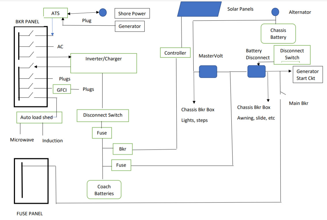
The Boost solenoid, the relay that combines the chassis battery and the coach batteries, to allow both to charged by the alternator. This is another case of when, and not if, the part will fail. When the relay fails, the coach batteries will not charged by the alternator. This is occasionally difficult to diagnose if the motorhome is always plugged into line voltage, the generator is used extensively, or the motorhome is equipped with a solar charging system.

The original relay, a Trombetta, can be identified by the single small gauge electrical post on the front of the relay. The replacement, a Cole Hersee 24213, has two small gauge posts on the body of the relay. The case of the Trombetta’s was used as a ground, and the single small gauge post was used to activate the relay.  The Cole Hersee 24213’s case is not used as a ground, and has two small gauge posts, and a ground wire must be connected to one post for activation. It does not matter which post is used for a ground.

Cabover Bunk

The Cabover bunk is affixed to the RV with two hinges and two gas struts. The hinges are actually hooks that clip over a rod and bracket fixture in the front of the Cabover. The gas struts hold the bed in place by pulling the bed to the rear, and keeping the bed hinge engaged to the rod and bracket fixture.

The original Cabover bunk mattress hinges were not designed properly. The old hinges do not have a welded gusset. The old style hinges are stamped and folded without the weld. As a result, metal fatigue causes the hinge to break and the bunk to come loose from the rod and bracket fixture. If one end of the bunk protrudes more than the other, or the bunk appears crooked, it is likely that the hinge is broken. The redesigned hinges have welds.

Additionally, the gas struts have enough holding power to keep the bunk in a raised position under all circumstances. The bunk need not be affixed to any of the clips in the roof. If the bunk slowly comes down, or comes down after a bump, the struts need to be replaced.

Microwave mounts

The microwave sits on a tray over the stove and is affixed to the RV by two vertical pieces of metal. Metal fatigue causes those vertical pieces, the mount, to fracture, and as a result the microwave is only attached by the bracket on one side. The tray and the trim assists in keeping the microwave from leaping from the cabinet, but the microwave should not be loose at all.

The repair has been made by purchasing nailing plats at a hardware store, and reattaching. Winnebago will also sell you the two mounting brackets.

Solar & Add On’s

It is easy to upgrade the 08 – 10 V/N’s so that they have more of the creature comforts that come standard in later models. It is east to add solar panels to the roof, and run the solar charging wired down the rooftop refrigerator vent. There are a number of articles on the View Navion Motorhomes Facebook Support site at http://www.viewnavionmotorhomes.com  that deal with solar charging systems, materials, and electrical consumption.

Systems

Slide Mechanism

The slide(s) on 08 -10’s are generally a single drive motor that engages a shaft with two drive gears. The motor has a lock that allows the motor to be disengaged from the drive shaft. The fit of the gears on the drive shaft to the track are loose enough, that the assembly requires no lubrication. To move the slide, the parking brake must be on, and it is recommended that the engine be running to supply sufficient energy to the slide motor. Additionally, there is a safety lock, that must be set to on. The safety lock was discontinued in later models.

If the slide cannot be retracted or extended, it is possible to extend or retract the slide by disengaging the slide drive motor, and using a crescent wrench to extend/retract the slide. The drive shaft is a square shaft.

Propane Appliances

It is highly recommended that the coach be fitted with screens over the propane furnace vents to reduce the chance insects will build a home in the orifice or flue. Occasionally either the propane furnace, refrigerator or propane water heater may not light. After checking to make sure that propane is available, the burner should be examined to ensure that nothing is shorting out the igniter, and that there are no cobwebs in the flue. Blowing out the flue with compressed air once a year, or as required is recommended.

Repair, Maintenance & Upgrade

The vehicle is out of warranty both with Winnebago and Dodge. It is not a Mercedes Benz product, although MB will gleefully provide service at great cost. After Mercedes Benz divested Chrysler, most/all of the Mercedes trained techs left Dodge and went to Mercedes Benz or an independent shop. If there were techs left behind at Dodge, it is likely that Mercedes Benz did not want them. Keep that in mind.

Additionally, any service provided by Mercedes Benz is warrantied in a different fashion than other MB products. Sedans and SUV’s have a 2 year, unlimited mile warranty on any work completed. Sprinters fall into the truck warranty of MB and are warrantied for three years or 36,000 miles whichever comes first.

Sprinters have been used in delivery fleets for years, so an alternate repair location would be a good truck repair company. Ask a Fed-Ex driver where they brought their Sprinter for service. A business that provides alignment services for 24’ box delivery trucks is an excellent place to have the vehicle aligned. When you align the RV, make sure that camber bolts have been installed. MB does not provide an incomplete chassis with camber bolts. Additionally the alignment location is an excellent source for recommendations on where to have the vehicle serviced.

Would you still bring your 13 year old Toyota to the dealer for routine service work?
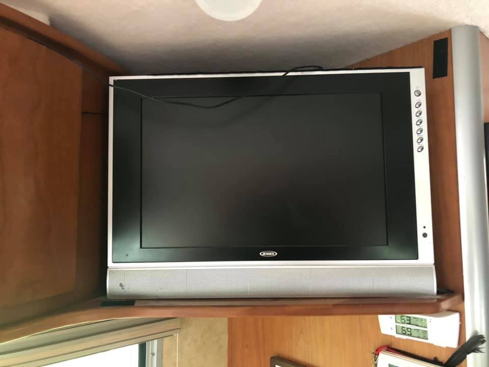
Television

The RV came equipped with a 12V flat panel television. There has been a significant change in televisions in the last 12 to 14 years. Over the air television broadcast still exists, however streaming, in place of cable, is gaining ground. Replacement of the TV with a smart TV is far easier than it seems. 12V televisions are available for anywhere from $275 to $600. An Insignia 1080p 120V television is available for about $160. The original TV came with a VESA mounting panel on the rear, so it’s a simple case of attaching a new TV to the old mounting plate.

The old 12V power cable can be used to attach a small 120V inverter (new TV’s draw an amp or less) that will turn on and off with the old TV power switch under the entertainment radio/DVD/CD device. The connections to the entertainment system are identical (an adapter may have to be used for audio).

To use the antenna, the booster should be on. It’s difficult to see, but there is a small black on black button on the faceplate that has the green LED on signal. A newer King Jack or Wineguard HDTV antenna is suggested as a replacement over the batwing TV antenna.

Towing and being Towed

Winnebago installed frame rail extensions to the chassis. The towing capacity of the coach is 3,500 pounds and the hitch weight is 350 pounds. Please refer to the GV weight when towing a vehicle.

If the RV is to be towed, it should not be placed on a flatbed, as the height of the RV and the distance off the ground combines to make the arrangement an oversized load.  The RV should be towed ONLY from the front, and only after the drive shaft has been disconnected. Towing from the rear has the potential of bending the frame rail extensions and bending/delaminating the coach body.

Capacities and Tankage

Fluid Change Description Part # Specification
Power Steering Fluid PRN Mobil ATF+4
Mopar
05013457AA 236.3
Rear Axle 10Y – 180K BP Energear Hyep DC 80W-90
Mobil Delvac Synthetic Gear Oil 75W-90
Mopar
04874469 235.20
Motor Oil 1Y – 10K There are many compatible oils. Check MB’s fact sheet (use the 229.52 oil)
NB* Torque the oil filter cap to 30Nm, 22 Ft#, and make sure the O ring is properly placed.
  229.51
229.52
Coolant 15Y – 180K; Thereafter
5Y – 90K
Zerex G05 – Valvoline
Zerex G48 – Valvoline
Mopar
05066386AA 325.0
Brake Fluid 2Y Intac B026E
Mopar
MS-9971
04549625AC 331.0
Transmission Fluid 60K Shell ATF 3403
Shell ATF 3403
Mopar
05127382AB 326.10
236.12
Fuel PRN Ultra-low-sulfur diesel (ULSD)

Do not add anything to the fuel, unless the vehicle will be operated at temperatures lower than 14֠ for extended periods of time. The fuel system has a fuel pre-heater.

   
Air Conditioning PRN Refrigerant R-134A    

Parts

Part

Capacity Description
Chassis Battery Cranking Amperage
~ 900A
Group 49 AGM Battery
H-8 AGM Battery
House Battery Total Usable AHr > 100 Type 31
Flooded, AGM, Dual 6V GC, Lithium
Lithium batteries require new converter, conditioning of the battery space, and a DC to DC Charger in place of the Boost Solenoid.
Fuel Tank 100L – 25 Gallons The tank includes a reserve of 20L, or about 5.3 Gallons
Windshield Washer 7.4 Quarts  
Headlamps   H7 Lamps for both high beam and low beam sockets. Current LED H7 lamps will fit in the low bean socket, but will not fit in the high beam space.
Fog lamps   H11 Lamps
Parking Lamps   WY5 Lamps
Turn Signal Mirror PY16
Turn Signal Headlamp Assembly PY21
Espar Heater   The Espar heater is located on the driver’s side of the cab, on the outer portion of the undercarriage, if equipped. The Espar heater burns diesel fuel to rapidly increase the temperature of the engine. There is a button on the left side of the steering wheel that is referred to as “Wavy Gravy” or “Bacon button”.


There is a thermocouple on the Espar heater. It will only turn on when the temperature is low.


Replacing Chassis Battery

By Don Paul
October 2, 2021

I just replaced our 8 year old original Mercedes (Varta) chassis battery in our 11VK with a $149.76 Platinum EverStart H8 AGM 5-year warranty battery from Walmart and learned a several things… So I’m posting a STEP-BY-STEP installation procedure to save others time & frustration:


  1. Walmart’s website shows “This item does not fit your 2011 Mercedes-Benz Sprinter 3500″… but it is WRONG. It fits perfectly. What’s really wonky is when you click their “Find Items that fit” link it shows their EverStart Maxx LEAD ACID (non-AGM) batteries “fit”… but these lead acid batteries NEED open air venting which our Sprinter’s battery compartments don’t have. DUH. They’ve got it BACKWARDS… Our V/Ns need AGM batteries !!!
  2. SAVE YOUR RECEIPT !!! You’ll need it if you have a warranty claim. I suggest taking a picture of your receipt and saving it on your phone… AND taping the receipt completely covered in clear packing tape to your battery compartment lid where you’ll be able to find it years from now IF you need it.
  3. Extracting the existing battery was a bit tricky since the positive cable/terminal has a bank of fuses attached to it which took some doing to finesse this fuse bank out of the way to get the existing battery out. YouTube video helped
  4. WAIT 10 to 30 minutes after you’ve turned your Sprinter OFF and removed the key to prevent getting a CEL (“Check Engine Light”) after you’ve installed your new battery
  5. Disconnect your chassis battery from the Sprinter chassis by pulling the plug next to the accelerator pedal. ALL your chassis lights should go out.
  6. Remove the (3) T25 bolts holding down the plastic L-shaped piece with a battery icon stamped on top. Don’t drop the bolts on the ground… You may never find them again.
  7. Remove the molded grey rubber floor mat. Yes it can get hung up but it does just pull out
  8. Loosen (no need to remove) the (4) Torx bolts (T25) holding down the metal lid of the battery compartment. Slide it aft to remove the lid.
  9. Remove the Red plastic cover over the Positive (+) battery terminal
  10. Loosen the 10mm nut on the Negative (-) terminal and remove the cable from the terminal. You may need to twist the cable to get is “unstuck” from the battery terminal.
  11. Unplug the existing AGM battery vent from the front of the battery. It just pops right out.
  12. Locate the black plastic handle for the battery hold down at the front of the battery bay. PAY ATTENTION TO WHICH WAY IT IS ORIENTED so you know which way it goes back in. (50% chance of re-inserting it incorrectly = 100% frustration… Think USB plug insertion frustration)
  13. Remove the battery hold down by completely loosening the bolts from their threaded sockets. The bolts should stay in the battery hold down. I needed a ~ 10″ extension on my 10mm socket and task lighting to remove the 2 battery bolts at the bottom front of the dark battery compartment. They came out easily and pulling the handle for the hold down lifts it up and out of the way with the bolts attached.
  14. Remove both the Positive (+) cable from the battery post by loosening the 10mm nut on each hold down, then twisting the battery cables up… and move them out of the way of your battery.
  15. Push the old battery forward FIRST to remove it since there’s a fixed hold down on bottom the aft part of the battery compartment. Again hard to see since this compartment has Black parts on Black compartment with poor natural light (chassis lights are off because the battery is dead / disconnected)
  16. You need to be flexible and strong to remove the ~ 60 lb. battery since the steering wheel is above the battery and the driver’s seat & base are in the way too. I’m 64 years young and fit (thanks mountain biking) so not a problem for me… but others may want to have Walmart or someone else install it for you. Walmart will probably charge since this installation is another Mercedes over-engineered PITA that takes time AND skill. IF you have someone else install it, be SURE they put the Red plastic plug in the aft vent hole (see below)
  17. Remove the new new battery’s Black plastic cap from the Negative (-) terminal and the Red plastic cover from the Positive (+) terminal. DON’T TOSS THE RED COVER AWAY… it has a small Red plastic plug you need to insert in the vent hole in the aft (+) end of the battery. This isn’t obvious unless you RTFM which is a TINY 1″x1″ yellow square taped to the side of the battery with print so tiny you’ll need a magnifier to literally “read the fine print”. LOVE my iPhone’s built-in Magnifier feature for tasks like this!
  18. Lower the new battery into the compartment. Mine wasn’t easy doing it solo since the vent tube kept flopping into the battery compartment in the front BELOW the battery as did the fuse block on the Positive cable in the back. Helpful to have another set of hands or secure these out of the way before inserting the battery… or Yoga move to tip the battery in the hole with one hand then grab the vent tube with the other while lowering the battery in. Who needs a Yoga workout or lift weights when Mercedes provided a Home Workout ??? LOL
  19. Move the battery forward to connect the Positive terminal / fuse bank.
  20. Push the battery aft to insert it under the fixed aft battery hold down.
  21. Reattach the Red Mercedes (not EverStart battery) plastic cover over the Positive (+) terminal / cables
  22. Connect the vent tube to the vent hole at the center of the forward (Negative terminal) side of the battery. Confirm the tiny Red plug is still in place on the aft (Positive terminal) side of the battery.
  23. Reinstall the battery hold down by FIRST finding the 2 battery hold down bolt holes and the centering gizmo at the bottom of the dark battery compartment. Then lower the hold down bracket into the compartment lining up the bolts with the black bolt holes on the floor of the poorly lit black battery compartment. Yoga helps since the driver’s seat base has a sharp corner which loves to poke ribs (I have a bruise to prove it LOL). Hand tighten the hold down bolts… and check your new battery won’t move
  24. Reattach the Negative (-) terminal.
  25. Recheck BOTH the Negative (-) and Positive (+) terminals are securely attached. Re-tighten just to be sure… You’re connecting a powerful 900 CCA diesel battery !!!
  26. Reconnect the Negative battery cable to the terminal by the accelerator pedal. Your Sprinter should lights come on. WINNING !!!
  27. Replace the metal battery cover by sliding the holes over bolts… then pushing it forward so the bolt heads are above the bolt slots. You may need to move the black (+) and red (-) cables to get it to go back on smoothly. Check to make sure none of your battery / chassis cables are going to be crimped when you tighten the Torx bolts to the cover.
  28. Replace the grey rubber floor mat. You may need to push it forward to get it to fit correctly in the back so you can…
  29. Replace the L-shaped piece with a battery icon stamped on top and reinsert the (3) T25 bolts holding it down. Don’t drop the bolts on the ground… You may never find them again.
  30. Celebrate / Medicate for a job well done.

https://www.walmart.com/ip/EverStart-Platinum-AGM-Battery-Group-h8/40647529

HOPEFULLY I didn’t leave any steps out… and I make no representations that I didn’t AND/OR these are the same steps you need to replace your Sprinter’s chassis battery. YMMV. If you’re not sure have a professional install it for you.


To Tow or Not to Tow?

by Larry Galantis – 18V
September 30, 2021

To tow or not to tow?- That is the question.

I think we all want to be as flexible as possible in our travels and sometimes the idea of towing a vehicle presents us with the illusion of flexibility.

It is my opinion however, that towing a vehicle does not necessarily increase your flexibility. In fact, it may even limit your flexibility.  My opinion is worth exactly what you paid for it. Certainly, I’m open to hearing yours. Of course, if you’re a full timer, a toad is almost mandatory.

In the interest of full disclosure, I have a tow vehicle but my opinions, stated below, may surprise you.

The decision to tow, I believe, depends on what type of traveler you are. Are you a “blow and go” traveler or a “stay and play” traveler?  Do you just blow into your destinations location, spend a day or two looking around, take a few pictures, click, click, click and then, you’re on the road again?  Generally speaking, if you’re blowing into a “destination location”, everything you might want to see is going to be right where you parked. If it’s not right there, it’s within walking or bicycling distance. Mt. Rushmore or El Capitan come to mind.

Or, is your RV travel style one where you drive into a town or destination spot and you stay in that spot for a week or longer while you really get into and take in the area?  Then, having a vehicle is probably a good idea. Notice, I didn’t say tow vehicle. Subject to availability, renting can be an option.

Here are a few reasons why I think the towing option is not as flexible as you might first believe.

  1. Deciding on and pulling into a fuel station becomes a little more complicated. It requires a little advance reconnaissance. Which island has the diesel dispensers? Am I going to be able to pull in and still have ample room to pull out? Many fuel stations today are nothing more than convenience stores that sell gas. Parking is set up with the convenience store customer in mind. Sometimes I’ve had to wait until several cars backed out of their parking spots so I had enough of a turning radius to get out!
  2. Simple tasks like making U-turns and backing up become more complicated when you tow. If you miss a turn, it’s not as easy to pull off a U-turn when you’re towing a vehicle. It’s doable but you have to select the right spot. Depending on the road you’re on, there may not be a shopping center or parking lot that you can pull into and turn around, for miles and miles.  Of course, you can always unhook and re hook.  Ask me how I know!

    Backing up, in many instances is not a viable option. Especially, if you’re flat towing.  Personally, I know some drivers will back up on a four down vehicle, But it’s not recommended. It’s very easy to bend those tow bars.

  3. Parking is a biggie. Stand alone, our 25’s are pretty easy to park and can fit in places that a rig pulling s toad, can’t.  Speaking of parking…..
  4. Sometimes, if you need to hook up, a park or campsite can generally accommodate a 25 footer. Add another 15 feet for your tow vehicle setup and now your site options become limited if not nonexistent.

    Not all camping facilities have pull through sites.  Yes, you can unhook your toad and back in but some campsites don’t have room for your rig AND a toad. Some National Parks come to mind. Besides, if you’re a blow and go traveler, connecting and disconnecting your tow car is just more work.  Even if you have it down pat…it’s still more work.

  5. Your travel expenses are going to increase. Be prepared for additional maintenance and repair costs for the toad.  Increased fuel costs as a result of reduced miles per gallon when towing. Add in additional insurance costs.   If it also does double duty as your daily driver, then some maintenance is still required, and tires will wear out sooner. Oh yeah, add a few bucks at the toll booth for those extra axles….
  6. You do ALL the driving. Some spouses/partners have no problem sharing the drive responsibility as long as it’s just the V/N.   Add a toad and you might be the sole driver.  Of course, many single drivers tow without trepidation.  Just sayin’ ….

Bottom line is that I can only think of 1 or 2 advantages to towing.  I can think of lots of disadvantages to towing. In the end, it’s up to you.

I’m up here in Indiana, 50 degrees and rainy. I can’t go sightseeing so I’m killing some time until I can get to my leveler install on Thursday.

By the way… don’t listen to me. I also own a boat. Has got to be the dumbest idea ever…..

Power Gear Programming

Power Gear Slim Rack Slide-Out Programming Procedure

By Brian Cummings
May 20, 2021

Use this procedure to SET the IN and OUT stops. Make sure engine is running during this procedure to ensure proper system voltage.

  1. Press and hold the IN button on the wall rocker switch. The IN stop must be set first.
  2. Move the room to the fully retracted position. Press and hold the IN button for 10 seconds after the room stops moving. Release the wall switch.
  3. Visually inspect the room seal to make certain the room is fully retracted. If it is not, repeat step 2. This procedure may need to be repeated until both sides of the slide out are fully retracted.
  4. You are now ready to set the OUT stop.
  5. Press and hold the OUT button on the wall rocker switch.
  6. Move the room to the fully extended position. Press and hold the OUT switch for 10 seconds after the room stops moving. Release the wall switch.
  7. Visually inspect the room seal to make certain the room is fully extended. If it is not, repeat step 6. This procedure may need to be repeated until both sides of the slide-out are fully extended.

NOTE:

The switch will need to be depressed and held down for 10 seconds after the room stops moving(or until you here both motors “click”) to correctly set the stop locations. This applies to both the IN stop (retracted) and OUT stop (extended). Failure to do so will cause the stops to NOT be set and the room will operate erratically and out of sync.

Highpointe Microwave Oven Quick Reference

By Kent Kyburz
March 20, 2021

 Microwave (1000W):

Set Cooking time
Press Start/+30SEC button
To adjust power setting press POWER repeatedly to reduce 20% each press.

Grill/Micro + Grill Combo Cooking

Press GRILL button repeatedly
G-1 100% Grill No Micro
G-2 2/3 Grill 1/3 Micro
G-3 1/2 Grill 1/2 Micro
Set Cooking time
Press Start/+30SEC button
Oven will beep twice at halfway point to indicate time to flip food.

Convection Cooking

With preheat:

Press CONVEC button
Press Convection TEMP key for proper temp
Press Start/+30SEC button to start preheating
Oven will beep twice when at temp.
Set Cooking time
Press Start/+30SEC button

Without preheat:

Press CONVEC button
Press Convection TEMP key for proper temp
Press CONVEC button to confirm temp
Set Cooking time
Press Start/+30SEC button

Convection Roast Cooking (Convection + Microwave)

Press ROAST button
Press Convection TEMP key for proper temp
Press ROAST button to confirm temp
Set Cooking time
Press Start/+30SEC button

Defrost

By weight:

Press DEFROST button once for DEF-1
Set weight in ounces using number keys (4-100 oz)
Press Start/+30SEC button

By time:

Press DEFROST button twice for DEF-2
Set Defrost time
Press Start/+30SEC button

Speedy Cooking

Press 1-6 to set number of minutes at 100% power.
Add 30 seconds with each press of Start/+30SEC button.